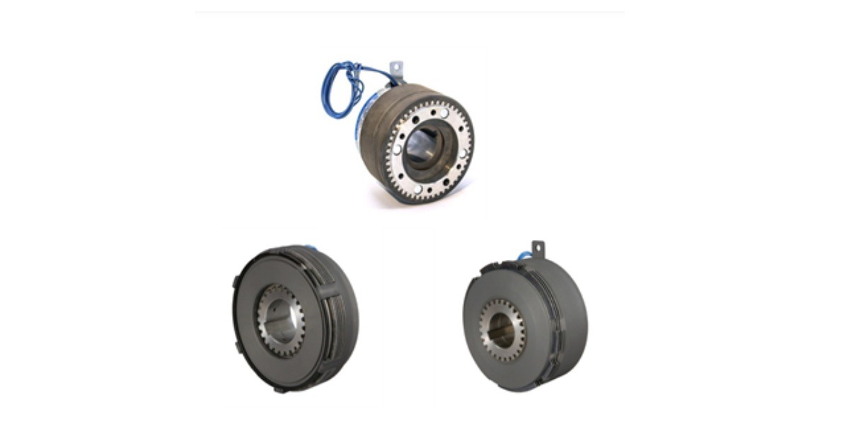
Electromate: High-Torque Electromagnetic Clutches – Multiple Disk & Tooth Designs for Demanding Industrial Applications
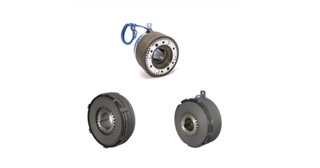
September 8, 2026
High-Torque Electromagnetic Clutches: Multiple Disk Clutches, Multiple Disk Brakes & Tooth Clutches
When torque requirements exceed what a standard single face electromagnetic clutch can deliver — or when the available envelope simply doesn’t have room for a large-diameter friction face — engineers reach for the high-torque side of the Ogura catalog: multiple disk clutches, multiple disk brakes, and tooth clutches.
These are not simply “bigger” versions of standard electromagnetic clutches. Each type achieves high torque density through a fundamentally different mechanical architecture, and each carries specific application constraints that determine whether it is the right fit for a given design. Getting this selection right — especially for tooth clutches, where a single specification error can result in a costly failure — requires understanding both the engineering advantages and the operating boundaries of each type.
This article covers multiple disk and tooth electromagnetic clutches and brakes in full detail: how they work, what they’re rated for, where they’re used, and the critical sizing parameters engineers need to get right before placing an order.
Why High-Torque Clutch Designs Exist
The torque capacity of a single face electromagnetic clutch is primarily determined by two factors: the friction coefficient of the engagement surfaces and the normal force pressing those surfaces together. The normal force, in turn, is limited by the magnetic flux the coil can generate across the air gap — which scales with coil size and rotor geometry.
For a given outer diameter and coil package, there is a torque ceiling. A machine tool gearbox shaft, a heavy conveyor drive, or a crane hoist may require torque levels that would demand an impractically large single face clutch — one whose outer diameter creates mounting and inertia problems, or simply won’t fit in the available mechanical space.
Multiple disk and tooth clutch designs solve this problem through different strategies. Multiple disk designs multiply the number of friction interfaces, getting more torque from the same radial footprint. Tooth designs abandon friction entirely in favor of a positive mechanical interlock, achieving the highest torque density of any electromagnetic clutch architecture.
Multiple Disk Electromagnetic Clutches
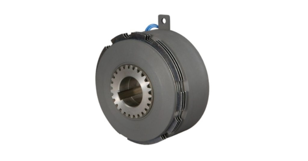
A multiple disk clutch contains a set of alternating inner and outer friction disks arranged axially within the clutch bore. Inner disks are splined to the input rotor and rotate with it. Outer disks are splined to the output member (or clutch housing) and rotate with the output. When de-energized, the disk stack is unloaded, and the disks can rotate independently — input spins freely relative to output.
When the coil energizes, the magnetic circuit attracts the armature, which compresses the entire disk stack between itself and the rotor face. Every friction interface in the stack — and there may be four, six, eight, or more — sees the same normal force simultaneously. The total torque transmitted is the sum of contributions from every interface.
This is the torque multiplication mechanism: the same magnetic force that would produce one friction interface in a single face design now produces multiple interfaces in the disk stack, each contributing proportionally to total output torque. Outer diameter stays the same; torque capacity increases with the number of disks.
Engagement Characteristics
The engagement behavior of a multiple disk clutch differs from single face in two important ways.
First, engagement time is slightly longer. The disk stack has higher rotational inertia than a simple armature plate, and the magnetic force must accelerate this mass during the engagement transient. For most applications the difference is small, but in extremely high cycle rate applications — where a single face clutch’s 20 ms engagement is already at the edge of the cycle budget — it is worth confirming with the actual application timing data.
Second, heat distribution during engagement is different. Each friction interface in the stack absorbs a share of the engagement energy — the heat generated during the brief slip period as output accelerates to match input speed. Distributing this heat across multiple surfaces rather than concentrating it at a single face allows the clutch to handle higher engagement energy per cycle, or higher cycle rates at a given energy level. This is one reason multiple disk clutches are preferred over single face designs in high-torque, moderate-to-high cycle rate applications.
Drive Hub Requirement
One detail that matters at installation: to function as a clutch (transmitting torque from input to output), a drive hub is required. The hub connects the outer disk pack to a pulley, sprocket, gear, or coupling that drives the load. Without a drive hub, the outer disk pack has no output connection and the device functions only as a brake. Ogura’s product pages specify which drive hub options are available for each series — confirm this during the selection process to avoid surprises at assembly.
Key Applications
- Machine Tools – Clutching high-torque spindle or feed drives in compact gearbox envelopes where single face designs would require too large an outer diameter
- Packaging Machinery – Applications where cycle torque exceeds single face capability and outer diameter constraints rule out upsizing
- Industrial Presses – Engagement of ram drives requiring high torque in controlled, repeatable fashion
- Multi-station Printing Presses – Drive selection between stations with differing torque demands
- Conveyors Handling Heavy Materials – Starting high-inertia belt loads requires peak engagement torque that single face designs cannot deliver in a reasonable package size
Multiple Disk Electromagnetic Brakes
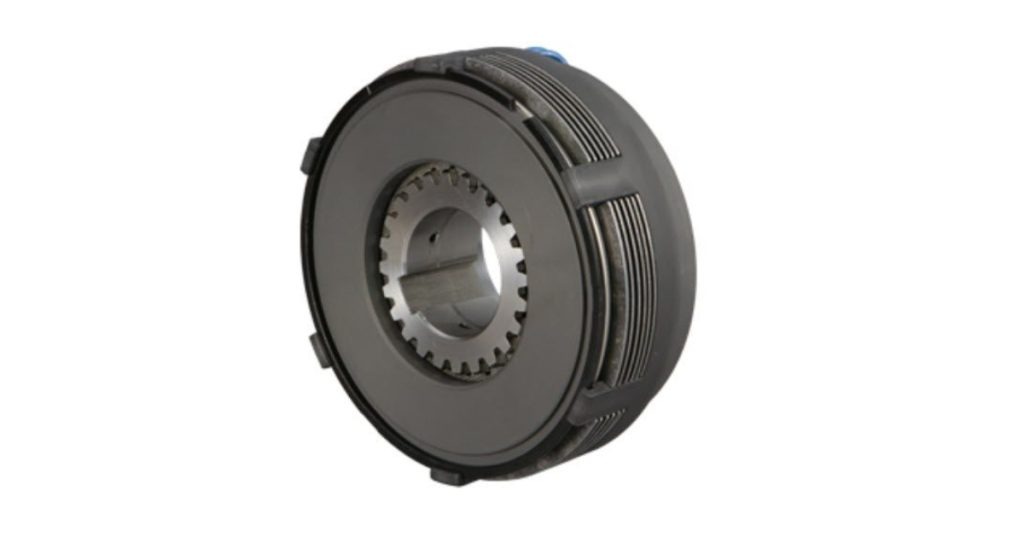
In the multiple disk brake configuration, the outer disks are anchored to a stationary housing rather than to a rotating output member. The shaft to be braked drives the inner disk pack.
When the coil energizes, the armature compresses the disk stack against the stationary housing face — the friction between rotating inner disks and stationary outer disks arrests shaft rotation.
The physics are identical to the clutch; the functional difference is that one side of the engagement is fixed to ground.
Everything that makes multiple disk clutches better than single face clutches at high torque applies equally to the brake version; plus one additional advantage specific to braking.
Thermal Advantage in Braking Applications
Braking converts kinetic energy to heat at the friction surfaces. In high-energy braking applications, stopping a heavy conveyor from full speed, bringing a crane hoist to a controlled halt, or emergency stopping a large inertia load, this heat can be significant. Single face brakes concentrate all of this energy at one friction interface. Multiple disk brakes distribute it across all interfaces in the stack.
More surface area means lower temperature rise per surface per stop, longer friction material life, and greater ability to handle repeated high-energy stops in succession without exceeding thermal limits. For applications with frequent emergency stop requirements, this thermal advantage is often the deciding factor in specifying multiple disk over single face.
Key Applications
- Overhead Cranes and Hoists – Braking torque requirements and energy absorption demands that exceed single face capability; often required to meet lifting equipment safety standards
- Marine Vessel Auxiliary Drives – Compact braking in constrained machinery rooms where radial space is limited
- Heavy Conveyor Systems – Emergency stopping of high-inertia loads, particularly on inclined conveyors where gravity assists runaway risk
- Industrial Winches – Controlled deceleration and load holding under high torque
- Construction Equipment Drives – Auxiliary equipment braking where mounting space and torque requirements both push toward disk designs
Electromagnetic Tooth Clutches
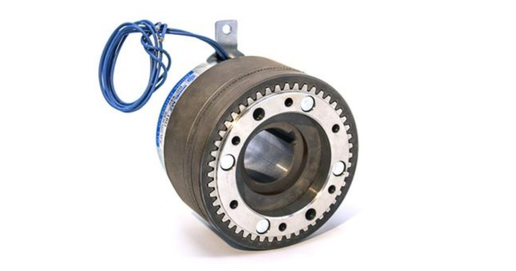
Tooth clutches are categorically different from friction designs — not a variation on the same theme, but a distinct mechanism. Rather than transmitting torque through friction at a contact face, tooth clutches use interlocking teeth machined into both the rotor and armature faces. When the coil energizes, the armature is drawn axially toward the rotor and the teeth mesh. Torque is transmitted through direct mechanical interlock — metal tooth against metal tooth.
The consequence is absolute: zero slip. Not low slip. Not controlled slip. Zero. Once the teeth are engaged, input and output are mechanically locked together. No relative motion is possible until the coil is de-energized and the armature disengages. Torque transfer efficiency is 100% — no friction losses, no wear at the engagement interface during running (wear occurs only during the engagement and disengagement transients, when teeth must mesh and unmesh).
Ogura’s MZ series is the definitive tooth clutch product line. Three components — field, rotor, armature/hub — in a package that delivers 25 to 4,000 Nm (18 to 2,950 lb-ft) of torque. This is the highest torque-per-size of any electromagnetic clutch design in the Ogura catalog, and by a meaningful margin.
The 30 RPM Engagement Limit: Why It Exists & Why It Matters
The tooth clutch’s defining limitation — maximum engagement speed of 30–50 RPM (varying with inertia and load torque) — is a direct consequence of its engagement mechanism. This is not a soft recommendation but a hard physical constraint, and understanding why it exists is essential to applying tooth clutches correctly.
When a tooth clutch is called to engage, the rotor teeth and armature teeth are spinning at different speeds (or one is stationary). The magnetic force draws them together axially. For the teeth to mesh cleanly, a tooth on the armature face must slide into a gap between teeth on the rotor face as the axial engagement occurs. If the relative rotational speed between the two faces is low — below 30 RPM — this happens smoothly. The tooth enters the gap, the faces come into full contact, and engagement is complete.
If the relative speed is high, the geometry is different. A tooth on the armature face approaches the rotor face, but before it can enter a gap, the rotor has rotated enough that another tooth is in the way. The armature tooth strikes the face of the rotor tooth — an impact load rather than a mesh. At 30 RPM this is manageable. At 300 RPM it destroys the tooth geometry within a small number of engagements.
The application implication is absolute: any system using a tooth clutch must include a mechanism — machine sequencing, speed sensing, or drive control logic — that guarantees the engagement signal is only issued when shaft speeds are below the maximum engagement RPM. This is standard practice in machine tool gearbox design, where the CNC controller manages the speed reduction sequence before commanding a gear ratio change. It must be explicitly designed into any new application.
Zero Backlash & Precision Indexing
For applications where positional accuracy is a design requirement, the zero-slip, zero-running-wear characteristics of tooth clutches offer an advantage beyond torque density. Friction clutches, even when properly sized, accumulate small amounts of position error over time as the friction surface wears and engagement characteristics drift slightly. Tooth clutches do not — the positive interlock maintains the same angular relationship between input and output every engagement, for the life of the unit.
This makes tooth clutches the preferred choice for precision indexing applications where angular positioning error must remain within tight bounds across millions of cycles. Machine tool rotary tables, precision indexers in automated assembly, and rotary transfer machines are typical application examples.
Key Applications
- CNC Machine Tool Gearboxes – Spindle speed range selection, programmed ratio changes; the CNC control architecture naturally accommodates the low-speed engagement requirement
- NC Lathes and Milling Machines – Gear ratio selection under CNC control
- Servo and Brake Motors – AC, DC, brushless DC, and servo motors with integral electromagnetic tooth clutches for high-torque axis drives
- Precision Rotary Indexers – Automated assembly systems requiring repeatable angular positioning across high cycle counts
- Gearbox-integrated Drives – Any gear-change mechanism where maximum torque density in the gearbox envelope is a design priority
Comparing Tooth to Friction for High-Torque Applications
When should you choose a tooth clutch over a multiple disk design? The answer comes down to three questions:
Can you guarantee engagement below 30–50 RPM? If yes, tooth is viable. If no, tooth is not the right choice regardless of torque requirements.
Is zero slip a requirement? If the application cannot tolerate any input-to-output slip — even the transient slip during friction clutch acceleration — tooth is required. If managed slip during acceleration is acceptable, multiple disk is a simpler, lower-cost solution.
Is torque density the limiting factor? If the multiple disk design that meets the torque requirement fits within the mechanical envelope and cost budget, there is no engineering reason to use a tooth clutch. If the required torque level exceeds what multiple disk can deliver in the available space, tooth is the solution.
All three conditions pointing toward tooth? Specify the tooth clutch. Any condition pointing away from tooth? Specify multiple disk.
Related Posts
- Spring Applied & Power-Off Permanent Magnet Brakes: Engineering Failsafe Motion Control
- Industrial Friction Clutches and Brakes: Single Face, Multiple Disk & Tooth Types Explained
- Ogura Electromagnetic Clutches & Brakes: Which Type Do You Need?
For more information on Electromate solutions HERE


Electromagnetic Electromagnetic Electromagnetic Electromagnetic Electromagnetic Electromagnetic Electromagnetic Electromagnetic Electromagnetic Electromagnetic Electromagnetic