Lean Robotics: Making Robots Work in Your Factory Part 2
March 23, 2021
DEPLOYING YOUR ROBOTIC CELL
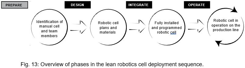
Let’s start by looking at the complete robotic cell deployment cycle, as shown in Fig. 13.
PREPARE
When you decide to deploy a robotic cell, it’s usually because you’re aiming to solve some issues in your company regarding productivity, quality, or output capacity.
In the project definition phase, you should identify the scope of your project. This includes:
- – The specific manual cell you intend to
- – The metrics you want to
- – A timeline for the
Once these have been defined, the next steps are to assemble your team and communicate these goals before you officially launch the project.
ASSEMBLE THE TEAM
Who will be kept informed about the robotic cell deployment project? Who will be put in charge? And who will actually carry it out?
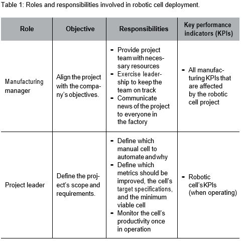
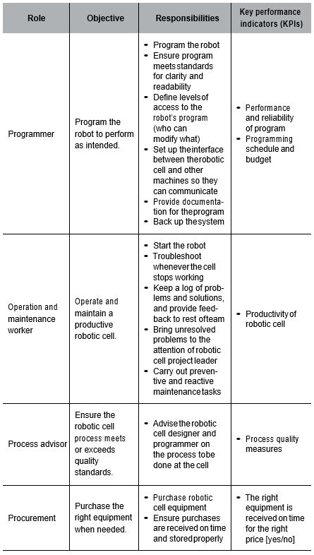
Table 1 lists all the roles people will play in a robotic cell deployment project. To keep track of who’s responsible for what, you could add a column on the right and fill it in with the name of the relevant team member. A template is available on leanrobotics.org.
In larger organizations, people’s roles might seem to be predefined by their job titles. However, several roles might still be played by the same person, as is often the case in smaller factories. I’ve even seen shop owner-operators do every single task by themselves.

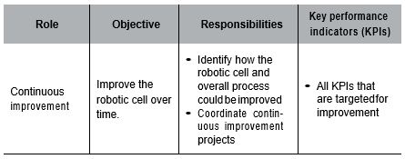
Sometimes the job title alone doesn’t capture all the responsibilities of a role. In these cases, people might overlook some crucial tasks.
For instance, the manufacturing manager is responsible for commu- nicating news about the project to everyone in the factory. This isn’t about saying “We’re installing a robotic cell. Deal with it.” Managers have to define the project’s raison d’être—the reason why robots will benefit everyone in the company—and ensure everyone understands it. (I’ll go into more detail on how to do this in the next subsection.)
On another note, sometimes people underestimate the importance of certain roles, such as the project leader. Since deploying your first robot involves innovation and change, you need strong leadership— both technical and managerial.
Don’t ignore the process advisor, either. It’s easy to overlook small steps in the manual process, especially with value-added processes like assembly, welding, or polishing. Casual statements like “By the way, once in awhile I have to hammer this corner to get the jig in” or “Oh yeah, sometimes I manually remove the extra burr so I can assemble the two parts” might seem insignificant, but if the robotic cell isn’t set up to do these tasks, the whole project could fail. That’s why you need a process advisor who will pay close attention to everything your current operators have to say about their jobs. In fact, the operators of the current manual cell usually make the best process advisors.
Lastly, don’t assign critical deployment tasks to people who are already 100% dedicated to other important projects in the factory. Be realistic about how many tasks each team member can take on. No matter how big or small your organization is, you might need to bring in new people.
Manufacturing managers, this section is for you. One of your most important jobs is to explain what’s happening with the robotic cell deployment in a way that’s compelling yet free of bullshit.
If you don’t tell people what’s going on, they’ll tend to assume the worst (whether in robotic cell deployment or life). And once these misperceptions spread, they’re hard to get rid of. It’s much easier to simply provide the right information in the first place.
Get your facts together and communicate your vision early and often— better to lean towards too much communication than too little.
START BY GATHERING THE INFORMATION
Once the project has been defined and team members selected, you should prepare a brief document or presentation that outlines the following:
- – Why—Figure out why the company is investing in robotics before you discuss how you’ll go about doing it. When people understand the “why,” they’ll be able to better contribute to the “how.”
- – Scope—What is the cell (or activities in a cell) to be automated? Where does the cell start and end, in terms of the production process?
- – Schedule—On what (target) date will the cell be up and running? How about the main steps in between—when will they be completed?
- – Roles—Who will be assigned to each task? What is each person responsible for, exactly?
For the moment, the purpose of this document is just to help you keep track of important information. Later, you will present it at the project’s announcement session.
NEXT, DEVELOP A STRATEGY FOR ANSWERING QUESTIONS
It helps to conduct a frequently-asked-questions brainstorming session with your management and HR teams before you announce the project. Do your best to predict all the questions people might have about the project, and have your answers ready.
Typical questions might be:
- – Will I be safe around the robot?
- – What will I do during the project?
- – If the robot does this task, will there be anything left for me to do?
- – Are you planning to lay off all the employees?
Consider the people who will probably be most concerned about the project, and figure out how you’ll respond to their anxiety. You might be able to work with your HR department to support workers who might be negatively impacted by the introduction of robots.
Also, even if most people understand why their employer wants to make a change, they’ll still be asking themselves “What’s in it for me?” It’s a fair question, and you should be proactive in answering it.
One great tool for answering questions is video case studies that show workers, engineers and managers discussing their previous concerns, how they accomplished the cell deployment, and what effect it had.
LAY THE GROUNDWORK WITH MOBILIZERS
Whenever a project is being “sold” internally, mobilizers are the people with the biggest influence on project dynamics.
Before kicking off the project, you might want to invest some time in meeting with your mobilizers as well as the workers you think could be most concerned about the changes the project will bring for them.
The goal here is to prevent yourself from hosting a meeting to announce the project where all your employees hear is “Robots are coming whether we like it or not.”

ANNOUNCE THE PROJECT
At the kickoff session, you’ll present the integration project as a mission to be accomplished. Gather everyone involved in the project, and explain what each person (or team) will work on and why it’s important. You can start the meeting off in a conference room, but it’s often a good idea to go to where the action will take place, namely the relevant station on the factory floor.
This is where you’ll present that information you prepared earlier (in the “gather information” step).
Remember that your audience might not have the same background information as you, so avoid jargon, particularly when it comes to technical terms.
Of course, your job doesn’t end here. You should keep people updated on the cell deployment’s progress, and share what an impact it’s had once the robotic cell is fully in production.
PHASE 1: DESIGN
You’ve done the prep work, and now it’s time to enter the design phase. When I say “prep work,” what I mean is that the design phase’s input consists of:
- – The definition of the project’s scope
- – Your schedule
- – Your list of team members and their roles
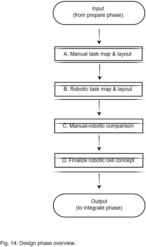
In this section, you’ll be working through the following steps:
- 1. Manual task map and layout
- 2. Robotic task map and layout
- 3. Manual-robotic comparison
- 4. Finalize the robotic cell concept
When you’ve completed these steps, what you’ll have is the design phase’s output:
- – The robotic cell plan
- – The equipment for the robotic cell—delivered and ready to be assembled
Fig. 14 depicts a flowchart of the design phase.
Let’s start with those two “mapping” steps, manual task mapping and robotic task mapping. These maps have the same underlying philos- ophy as lean manufacturing’s concept of value stream mapping (see glossary).
In lean manufacturing, every improvement project starts with a map of the current value stream (see Fig. 15).

Using Fig. 15 as an example, here’s how the map is created:
1. Identify who the customer is for a specific process and how the customer defines value. In this example, the “customer” is the shipping department. What the shipping department needs is 50 parts a day.
2. Break the process down into its various steps. Within each step, identify value-added and non-value-added tasks, and measure how long they There are three main steps in our example: blank prepara- tion, machining and quality assurance. For each of them, it’s possible to measure the time of value-added tasks and of non-value-added tasks. The time to transport the parts from one step to another is also noted. A line at the bottom of the map illustrates the total cycle time of each step and the value-added time portion of it.
3. Describe what (and how) information is transmitted among the different participants in the value creation In this particular machine shop, the production control will receive information electronically from the shipping department requesting the parts. This in turn will send information electronically to the warehouse team so they will prepare their delivery to the blank preparation operator. The machining center sends back some information to the production control electronically for traceability purposes.
Once you have the initial value stream map, you can create a new map of the ideal process. The “current” map and the “ideal” map are the basis of your project plan.
That’s exactly what we’re going to do for your robotic cell. In lean robotics, the “current” map is of the manual task map, and the “ideal” map is of the robotic task map.
The manual task map will be your starting point for understanding how the existing output is produced. Then your robotic task map will define how the robot can produce your desired output.
Once you have the two maps, you can proceed to the manual-robotic comparison step, where you’ll find out what you need to do to transi- tion to a robotic cell.
A. MANUAL TASK MAP AND LAYOUT
One trap we too often fall into is starting to look for a solution without having clearly defined the problem. We jump back and forth between trying to understand the current process and suggesting technical ways to accomplish it with a robot, which very soon becomes con- fusing. We should start by doing the manual task map, which is a static snapshot of the starting point from which we will work to improve.
Manual task mapping is a lot of work up front, but it will save you far more work down the road by letting you see the problem more clearly and have all the important information at hand. By documenting the manual task first, you’re helping break a bigger problem down into a set of smaller problems.
MANUAL TASK MAPPING STEPS
Whenever I visit a company looking to install their first robot—and I’ve visited hundreds over the past decade—it goes something like this. We sit down, the manufacturing engineers explain why they’re inter- ested in robots, and then we tour the factory floor.
I’m often bombarded with questions like “Look at this station, how could I do this with a robot?,” “It’s a pain to do this task, how can I get a robot to do it?,” “How easy is it to add a robot here?,” and so on.
To answer these “how-to” questions, we first need to take a step back and answer some questions in order to fully understand the current process. These questions are the same ones you need to answer to complete the manual task map.
The manual task mapping process is like taking the value stream map and zooming in on a particular manual station. This mini value stream map describes the same things as the larger one it is part of: who the customer is, how the customer defines value, which steps are involved, whether or not those steps are value-added, and how the information is transferred. These things constitute the value creation information.
There is one difference from a typical lean manufacturing value map, though. Although we’ll be focusing on value creation in the manual task map, we also need to capture information necessary to later develop a concept of how a robot could do these tasks. Even though this robotic constraint information isn’t technically relevant to under- standing the value creation, we need to take notes on some specific aspects that will impact the robotic cell design, because robots cannot do everything that a human can do.
Capturing the information in the manual task map will save time in the later phases. The way it’s structured (as shown in Fig. 16) means you gather all the relevant information—no more, no less—on the first pass. It will help you capture pieces of information that might seem like trivial parts of the manual process at first, but that will later prove crucial when attempting to do the same task robotically.

First, each step will be explained in more detail below. Then I’ll walk you through an example.
1. IDENTIFY CELL CUSTOMER
The manual task map begins with the end of the process. This is aligned with the lean robotics principle of focusing on the robotic cell’s output.
It might seem more intuitive to define the steps chronologically, starting with the first operation actually done at a station. But starting with the end means we focus on the real result we want to achieve: creating value for the next manufacturing step. It’s important to keep this in mind to avoid getting lost in technical details of the process. In a factory, a manual station’s customer is the next operation in the manufacturing flow. If your value stream map is the larger version that includes the manual process, the customer should be obvious: it’s the operator or machine that receives the parts from the station.
2. DEFINE VALUABLE OUTPUT
Defining valuable output means answering this question: what input does the cell customer need?
Put yourself in shoes of the operator (or machine) who receives the parts, and complete the sentence “As the manual cell’s customer, I need it to give me so I can .” For example:
- I need it to give me clean, visually inspected casing that arrives by conveyor belt every five minutes so I can assemble product SKU
- I need it to give me part #AGS-002 with tolerances of .01 mm in that specific dimension every 30 seconds, placed on a fixture so the machine can do the surface
- I need it to give me a 10-layer stack of 20 x 20 cm trays filled with part #DJ2-3322 so I can package them for shipment to the external
When you figure out the what (“I need…”) and the why (“so I can…”) of the next step in production, you’ll uncover information that will have a significant impact on the robotic cell that will be doing this task.
Make sure you consider the cell customer’s perspective when distin- guishing the “need to have’s” (what’s absolutely necessary) from the “nice to have’s” (what could make the job faster, easier, cheaper, more fun, etc.).
It can also be helpful to make drawings, pictures, and videos of the output process when trying to capture information at this step.
3. DEFINE INPUT
The next step is to define what materials and parts are coming to the station, and how the parts are presented. In this step, you’ll aim to make a note of any information that could be relevant to your robotic cell concept.
Nature of the Part(s)
Here you’ll capture the following information:
- – Number of different parts
- › How many different parts are handled and/or pro- cessed at the station?
- – Characteristics of the parts
- › Dimension
- › Weight
- › Material
- › Other, if relevant
- – Variation in time
- › Are there changeovers at this station (in terms of the type of part being manufactured)? If so, how often?
- › Are you planning to manufacture new parts in the near future?
Drawings and pictures (including the correct scale) can work well, but may not be practical if you’re dealing with a high number of different parts. In this case you can write a list of all the parts and their main characteristics (e.g., the main dimensions, the weights, etc.). We’ve seen this several times with tier suppliers who always make the same type of parts but in different shapes.
In other cases, the challenge will be not knowing the exact nature of the parts you’ll be handling in the future, such as if you’re a contract manufacturer. You’ll want to work with a minimum and maximum range for various characteristics (min-max size, min-max weight, etc.). These projects often require tradeoffs. It’s very expensive to build a robotic cell that can handle both the bulk of parts (that are all the same general type) and the occasional outlier (that’s very different from the norm). So it might be better to reduce the scope of what’s automated while keeping a manual station at the ready for outliers.
For robotic cells that will do assembly tasks, this step will involve a great deal of information, since it has to be done for each individual input (parts to assemble, fasteners, etc.).
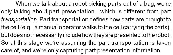
Part(s) presentation
In many applications, the robot’s main challenge isn’t handling or transforming parts—it’s simply being able to pick them up in the first place. As of the time of writing, robots still have a hard time dealing with unstructured things. If your parts arrive jumbled up in plastic bags tied with rope, it’s no big deal for a human operator. But for the robots of today, picking the right part out of that bag is a nearly impossible task, especially if you want it done in a consistent and timely manner.
When documenting the part presentation information, make sure you look at the following:
- – Are the parts singulated (individually separated with space all around them)?
- – How do the parts arrive?
- › One by one
- › Stacked on top of each other
- › Arranged side-by-side
- › Placed randomly
- – Are they packaged?
- – Where are they?
- › On a table
- › In a fixture
- › In a tray
- › In a stack of trays
- › In a chute
- › In a bin (sorted or random?)
- – Are they moving?
- › No, they’re stationary when picked
- › Yes, e.g. on a moving conveyor
Until technology gets better, part presentation will often be an area where waste is added in the automation process to accommodate robots’ limitations. A typical example is adding the non-value-added task of structuring the parts’ presentation just so the robot can pick them. In this task, every time the robot is done working on a batch of parts, a human has to come and manually arrange the next batch to be worked on.
Again, pictures and videos work well to capture a lot of information related to part presentation.

4. DESCRIBE PROCESS
At this stage, you’re capturing information on everything that happens between two points: when the input parts arrive, and when the output parts are received by the next station.
This can be the trickiest part of the manual task mapping stage. Think of a manual faucet polishing application, for example. The manual operator will pick the part, adjust his moves from what he originally sees, and apply various forces at various speeds until the finished product looks good to him. How do you document and measure that process to eventually program a robot to do it?
There are infinite combinations of processes and parts, and what’s rel- evant for each of them will vary greatly. The good news is that even if you’re not an expert in robotics (yet!), you are an expert on your process.
Here’s what you can do to make it easier to create a manual process map:
- – Take Processes involve many dynamic interactions, so it’s a good idea to film the process from various angles.
- – Have the operator talk out loud and explain what he (or the machine doing the process) is Ask him why he does specific actions. Keep asking “why?” several times to try to uncover the root reason. When you know the underlying reason why something is done, you can start being able to figure out whether a robot could achieve the same objective another way.
- – Pay attention to hidden Some minor steps might be trivial for operators but surprisingly difficult for robots. These tasks may have become so ingrained in the operator’s routine that they happen almost subconsciously. A “hidden” task like this might be doing a visual inspection on a specific feature of a part, making sure there’s no more dust or oil at a given place on the part, or removing a burr on one part out of 100.
Once every step has been documented, identify which of them add value and which of them don’t, and measure the amount of time it takes to do them.
5. DOCUMENT FLOW OF INFORMATION
The flow of information happens between the cell and other parts of the factory, as well as within the cell.
What information comes into the cell? Is it transmitted electronically, on paper, verbally, or otherwise? How does it affect the task? How does the operator or machine know what to do and when to do it?
Ask the same questions for information that goes out of the cell. What information is generated at the cell that simply needs to be passed somewhere else? How is this information used afterwards? Is there information that’s not currently being transferred that could have a positive impact on other operations?
These questions also apply within the cell. What information needs to be passed between the operator and the machine?
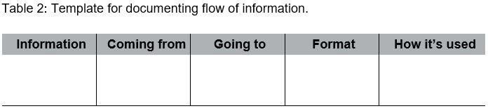
Create a table (like Table 2) with the information, showing where it comes from, where it goes, what form it takes, and what it impacts.
6. MEASURE CELL KPIs
Depending on what your goal is in using a robot for a specific station, you’ll want to measure certain key performance indicators, or KPIs. Even if certain KPIs are not your main target for improvement by the robot, they might still be important, so you should note their starting values and monitor whether they stay within an acceptable range.
For example, maybe your main goal is to increase output capacity, but you also want to maintain the current cost of making parts at this station. So you will obviously want to measure both metrics.
Table 3 summarizes a few examples of goals you might have and the corresponding KPIs to measure.

7. SUMMARIZE MAP
The last step of manual task mapping is to summarize the key infor- mation in a clear and concise visual representation. This will give you an overview of the manual cell that is to be improved; think of it like an executive summary comprising the core information of a more detailed report.
Fig. 17 shows how a manual task map summary might look (without the details filled in).
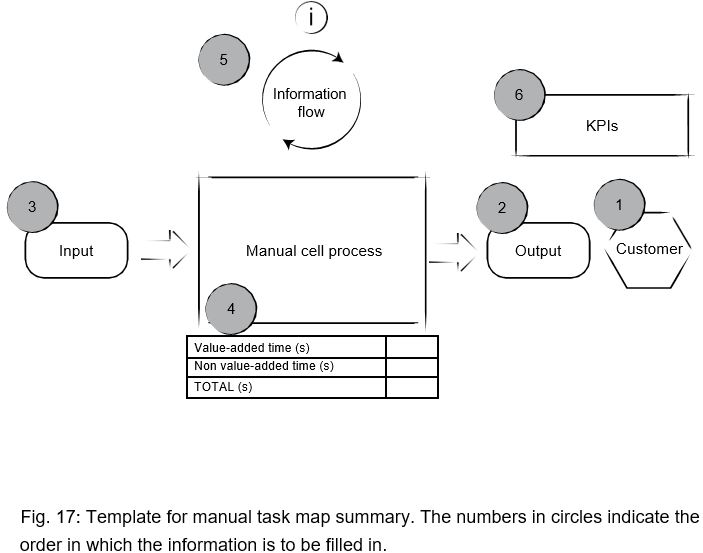
In the summary map, you’ll find references to all the information you gathered in the previous manual task mapping steps:
- – Customer
- – Valuable cell output
- › Customer’s desired input
- – Cell input
- › Parts
- › Presentation
- – Process
- › Value-added steps and time
- › Non-value-added steps and time
- › Total process time
- – Information
- › Going into the cell (with source) and out of the cell (with destination)
- › Exchanged within the cell
- – KPIs
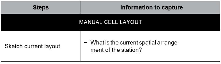
MANUAL CELL LAYOUT
Whereas the manual task map is about defining the current manual cell’s sequence of operations, here we describe its spatial layout.
Often there’s no work to be done here because businesses already have their cell layout documented. But if you don’t, it doesn’t have to be complicated: just make a bird’s-eye-view sketch showing the main things in the cell, and take photos to complement your drawing. On the sketch, you should also include the dimensions of the main components.
LEAN ROBOTICS IN ACTION
The Acme Corporation is a (fictional) large contract machining manufacturer.
Last year they had a big order to fill and had to scramble to increase capacity. Their machine could only produce so much during the day, so their options were to have someone work overnight, buy another machine to run during the day, or integrate a robot that could work day and night.
The first option was no good. It’s already hard to find good machinists, so they knew they’d struggle to hire one willing to work at night. Also, the machine they needed is expensive and has a long lead time. So they settled on the robot option, and had it up and running within a month.
How did they do it? Let’s start by looking at their initial process for creating their manual task map.
1. IDENTIFY CELL CUSTOMER
The cell customer is the operator who brings the machined parts to an inspection station.
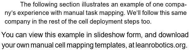
2. DEFINE VALUABLE OUTPUT
As the manual cell’s customer, I need it to give me…
→ a tray of 60 parts every 2 hours (specifically part numbers AGS202, AGS204, AGS225, AGS400),
so I can…
→ take the finished parts to the inspection station (see Fig. 18).
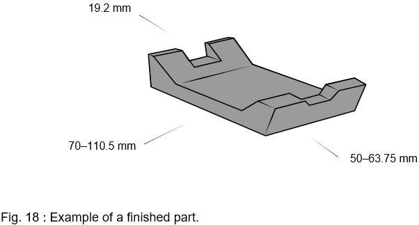
Part(s) presentation
The following questions relate to how the parts are arranged at output (see Fig. 19).
Are the parts singulated? How much space is around them?
→ The parts are stacked on top of each other.
How are they packaged?
→ The stacks of parts are on a tray.
Are the output parts placed onto a moving surface (e.g. a conveyor belt)?
→ No, they are placed on a stable surface (a tray on a table).
3. DEFINE INPUT
Nature of the part(s)

How many types of parts are there?
→ There are four different types of blanks.
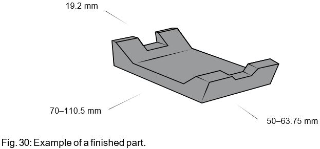
What are the parts’ characteristics?
→ See Fig. 20.
Dimensions:
→ Max: 110.5 mm x 63.75 mm x 19.2 mm rectangular blocks
→ Min: 70 mm x 50 mm x 19.2 mm rectangular blocks
Weight: Material:
→ Max. 0.36 kg
→ Solid aluminum
Are there changeovers at this station?
→ Yes, two to three times per week.
Are you planning to introduce new parts in the near future?
→ Perhaps in 9–12 months. There will be a similar kind of blank at input, and it will be within the min-max range defined above.
 Part(s) presentation
The following questions relate to how the parts are presented at input (see Fig. 21).
Are the parts singulated? How much space is around them?
→ They arrive stacked on top of each other.
What is the packaging?
→ The stacks are arranged on a table.
Are the input parts presented on a moving surface (e.g., a conveyor belt)?
→ No, they are presented on a stable surface (a table).
4. DESCRIBE PROCESS
The manufacturing engineer at Acme asked the operator to comment on the various steps in the process while he recorded a video with his phone. Since it’s a continuous process, he had to decide what to define as the starting point in the cycle. He chose the state of the system when a finished part is present in the CNC machine’s vise. So the first step is to open the machine’s door to remove the finished part.
The process is illustrated in Fig. 22.

Then each step was categorized as value-added or non-value-added, and the time to execute them was measured as shown in Table 4.

5. DOCUMENT FLOW OF INFORMATION
In the current setup, all the information is transferred manually. Table 5 summarizes the information needed at the cell.

6. MEASURE CELL KPIs
The most important performance indicators for the cell are:
- – First pass yield—97% (3% of the parts are rejected at the next station, which is quality inspection).
- – Real cell output—210 parts per
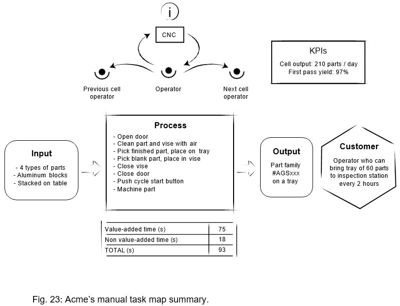
7. SUMMARIZE MAP
All the information gathered above can be summarized as shown in Fig. 23.
CELL LAYOUT
After summarizing the manual task map, Acme also gathered information on the spatial arrangement of the cell.
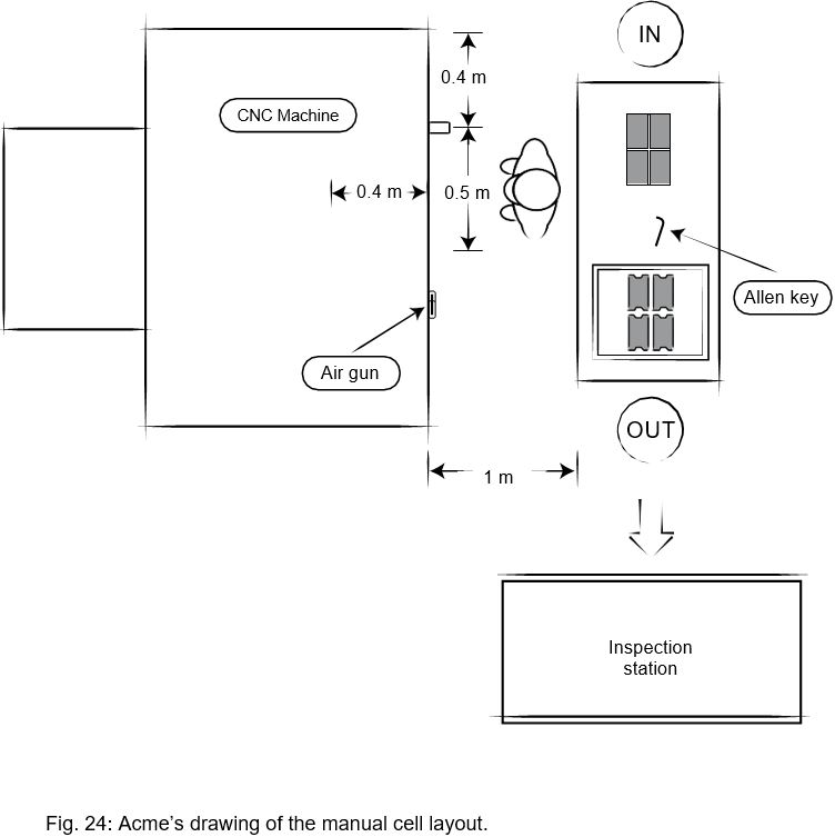

Visit leanrobotics.org to view the example above, and a template you can fill in, in slideshow form.
SUMMARY
In the table below, you can find a list of all the steps to be done for the manual task map and layout.

B. ROBOTIC TASK MAP AND LAYOUT
The thing about robotic task mapping is you can’t complete it without knowing the layout—but you also can’t complete the layout without knowing the task map! So you’ll be working on these two components together.
The robotic task map takes the same structure as the manual map, and is summarized in Fig. 26.
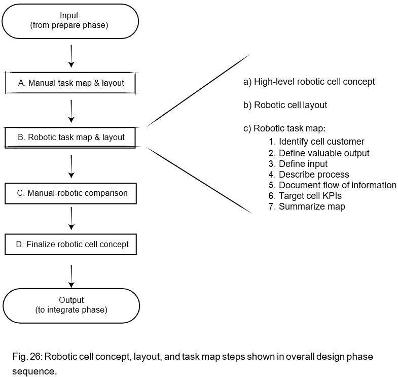
Before doing the robotic task map, you first need a high-level robotic cell concept that describes the cell constituents and task sequence.
HIGH-LEVEL ROBOTIC CELL CONCEPT
At this stage, you don’t want to do a detailed design of the robotic cell. The goal is just to have at least one cell concept that you’ll be able to compare with the current manual process so you can figure out if it’s worth pursuing the concept. Only then will you proceed to create a final robotic cell concept in all its glorious detail.
You start your high-level robotic cell concept work by identifying the main parts of the robotic cell that are not present in the manual cell. These components include:
- – The robot —Which brand and model of robot has the right specifica- tions for the process (reach, payload, speed, repeatability, compati- bility with tool, )?
- – Tooling—What tooling, both on the robot and elsewhere in the cell, is necessary for the process?
- – Sensors—Do you intend to do closed loop control or logic-based programming using sensor data? Sensors can be simple, like limit switches, or more complex, like vision systems and force-torque sensors.
- – Safety measures—Will you choose power and force limiting, fencing, safety sensors, or something else?
- – Software—Will you use external software to manage the process and/or program the robot?
You will have to evaluate the specifications of every component that will be added to the robot—the tooling, sensors, safeguards, and software.
You’ll also have to consider how these things will interface with your chosen robot. Don’t underestimate the effort (non-value-added effort!) needed to interface two machines that were not meant to work together.
The next step is describing the high-level sequence that the robot will do. The sequence description should include the following:
- – Part infeed technique—How will the parts be presented to the robot? This decision relates to your choice of tooling and sensors. You’ll need to find the right balance of cost, flexibility, and complexity for your
- – Part outfeed technique—How will the parts be presented to the cell customer? Can you even present the parts to the customer, or must you add an intermediary step between the robotic cell and the original customer (such as some secondary inspection task)?
- – Process sequence—How will the robot execute the process? Write the process down in bullet point
- – Information flow—What information will need to be exchanged within the cell, and between the cell and other parts of the factory?
ROBOTIC CELL LAYOUT
The cell layout is a bird’s eye view of the robotic cell showing how parts are placed with respect to each other and with their direct environ- ment in space. Use a representation with similar references as your manual cell layout so they’ll be easy to compare.
You probably drafted a sketch of the robotic cell layout while working on your robotic cell concept; but if you didn’t, now’s the time to create it.
ROBOTIC TASK MAPPING STEPS
The template for the robotic task map is the same as for the manual task map.
With the concept work done, by this point you’ll have defined a good portion of the information that will be included in the robotic task map. The robotic task mapping steps are where you’ll complete this information.
1. IDENTIFY CELL CUSTOMER
Sometimes certain aspects of the manual process are not good candidates for automation. You might realize you need to split up the process and robotize just a part of it, leaving the complex portion to an operator—in which case the robotic cell’s customer might differ from the manual cell’s.
For example:
- – Assembly—You map a manual assembly task that provides a com- pletely assembled product to its customer, a packaging The robotic cell you’re planning to implement can only do the first five assembly tasks, leaving the last two high-dexterity tasks to a manual operator. Here the robotic cell’s customer is the human operator, whereas the manual cell’s customer was the packaging station.
- – Inspection—The robot can do the value-added process (e.g., welding or polishing) but you still need a human operator to do a visual inspection of the In this case, the robotic cell’s cus- tomer is the operator who will do the visual inspection, whereas the manual cell’s customer was the station receiving the cell’s output parts.
- – Packaging—A robot might not be able to package the parts to be sent to the next station if they need to be precisely or tightly slotted into their packages. In cases like this, the robotic cell’s customer might be a human
It is possible to have things the other way around, if your robot is capable of doing more than the current manual cell process. When that happens, you can extend beyond the initial customer to a new one further down the line.
2. DEFINE VALUABLE OUTPUT
Even if the manual and robotic cells have the same customer, that customer might have different definitions of valuable output. This is especially true if one goal of the robotic cell project is to improve the value of the output.
You can still use the same structure to define the valuable output: simply complete the sentence “As the robotic cell’s customer, I need it to give me so I can .”
3. DEFINE INPUT
The reasoning that determined whether the robotic cell’s customer is the same as the manual cell’s also applies to the cell’s input.
If the parts were already being presented in a highly structured and accessible manner, you can probably use the same input. The more unstructured the part presentation method, the more likely it is that you will need to add a part preparation step so the robot can pick the parts reliably.
A part preparation step could be singulating the parts and placing them in a fixed tray or chute, for instance. Another approach is to use a sensing system, typically vision, so the robot can adapt to the unstructured part presentation.
4. DESCRIBE PROCESS
Describe the sequence of actions that will be executed in the robotic cell. Estimate how much time each will take, and indicate which are value-added and which are not.
If it’s your first project, it might be difficult to estimate the robot’s cycle time or use advanced tools like simulation software.
If you’re not experienced with estimating a robotic cell’s abilities and cycle times, take good notes on all the assumptions you’re making now. You can use this list of assumptions in the upcoming “de-risking the concept” step.
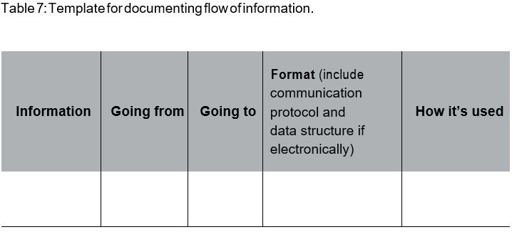
5. DOCUMENT FLOW OF INFORMATION
What information needs to come into the robotic cell so the robot can do the right task? Where will that information come from? What format will it be in?
- – If the format is electronic, you’ll need to define the communication protocol and data structure:
- › If the information is currently transmitted on paper or via a visual cue, will you need an operator to input it manually or trigger an action in the robotic cell?
- › What would it take to transmit it electronically or via sensors?
Ask the same questions for the information that goes out of the robotic cell:
- – What information is generated at the cell that needs to be passed somewhere else?
- – How is this information used afterwards?
- – What data structure and communication protocols can be used to do this?
- – Will new information be generated by the robotic cell that could have a positive impact on other operations?
Go over the same questions for the information exchanged within the cell.
Fill out Table 7 with where the information comes from, where it goes, what format it’s in, and what impact it has.
6. TARGET CELL KPIs
In the manual task map, you identified the KPIs you will track in order to measure the success of the robotic cell deployment.
Now, decide:
- – What are the targets for improvement—or the minimum threshold— for each of these KPIs?
- – How will you measure and monitor them once the robotic cell is installed?
- › For example, will you manually track them, add counters to the robot program, or have remote monitoring of your robotic cell?
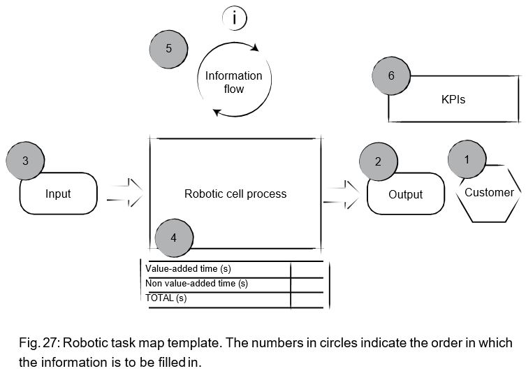
7. SUMMARIZE MAP
The final step is to summarize key information in a clear and concise visual representation, as shown in Fig. 27.
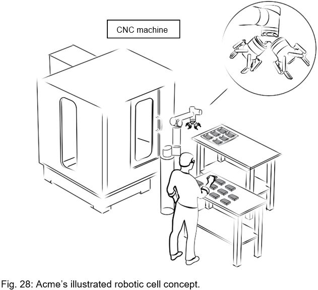
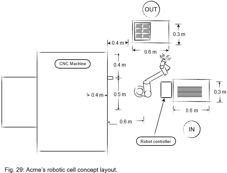
LEAN ROBOTICS IN ACTION
Acme’s high-level robotic cell concept is shown in Fig. 28. The cell concept includes the following components:
- • Robot
- › Model ABC from the W-bot brand was chosen due to its payload, reach, ease of use, and safety features that negate the need for fencing.
- • Tooling
- › Two grippers from supplier X will be installed on the robot wrist. This will enable optimization of cycle time. The grippers can accommodate the various sizes of input parts that vary from one batch to another.
- › An air gun actuated by an electric I/O will be installed under the gripper that picks the finished parts. The air gun will clean the fixed vise in the CNC before blank parts are placed in the vise by the other gripper.
- › In addition, the fixed vise will need to be converted to a pneumatic version that can be opened and closed via electric I/O.
- • Sensor
- › Because of the various input part sizes, Acme decided not to use fixtures to place the part at the input. To help pick them precisely, a camera from supplier Y will be installed at the robot’s wrist. Acme made sure the chosen camera has the stan- dard driver and mechanical interface to work on a W-bot robot.
- • Safety measures
- › Marks on the ground will indicate to the user that that he or she should not enter the robot’s work- space. Workers will be trained on safety measures, and instructed to use protective equipment such as glasses and hard-cap shoes. The robot’s move- ments will be limited to a certain speed.
- • Software
- › Standard W-bot software will be used for program- ming. Drivers from gripper company X and camera company Y are provided for the W-bot controller.
With this concept, the rest of the robotic task map can be completed.
1. IDENTIFY CELL CUSTOMER
The cell customer is the operator who brings the machined parts to an inspection station.
2. DEFINE VALUABLE OUTPUT
As the robotic cell’s customer, I need it to give me…
→ a tray of 60 parts every 2 hours (specifically part numbers AGS202, AGS204, AGS225, AGS400),
so I can…
→ transport them to the inspection station.
Are the parts singulated? How much space is around them?
→ The parts will be laid side-by-side on a table according to a matrix (rows and columns) with enough space in between each one for the gripper’s fingers to fit.
How are the parts packaged?
→ They are laid on a table.
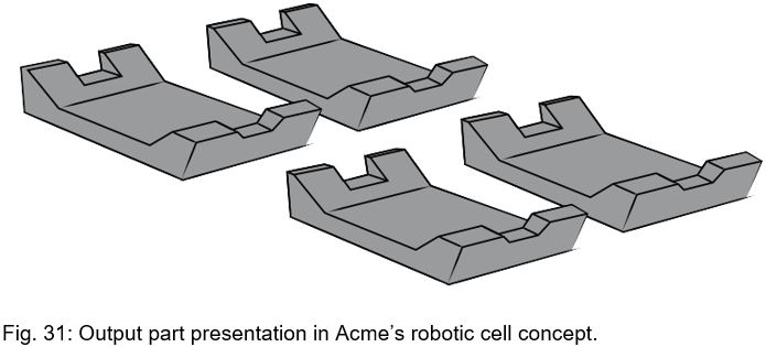
Are the output parts placed onto a moving surface (e.g. a conveyor belt)?
→ No, they are placed on a stable surface (a table).
3. DEFINE INPUT
How many types of parts are there?
→ There are four different types of blanks.
What are the parts’ characteristics?
→ See Fig. 32.
Dimensions:
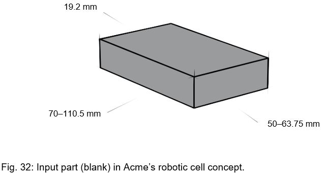
→ Max: 110.5 mm x 63.75 mm x 19.2 mm rectangular blocks
→ Min: 70 mm x 50 mm x 19.2 mm rectangular blocks
Weight: Material:
→ Max: 0.36 kg
→ Solid aluminum
Are there changeovers at this station?
→ Yes, two to three times per week.
Are you planning to introduce new parts in the near future?
→ Perhaps in 9–12 months. There will be a similar kind of blank at input, and it will be within the min-max range defined above.
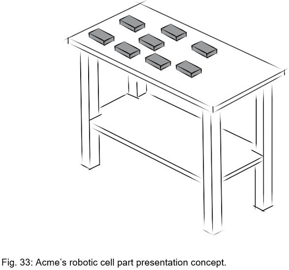
The following questions relate to how the parts are presented at input (see Fig. 33).
Their chosen part presentation concept is to position the parts on a table and use a camera to locate them. This method seemed to be more flexible than the alternatives, since the vision system can locate different parts automatically, whereas a hardware-only solution would require manually changing the physical setup to handle different parts.
Although they had a hunch this concept would work, they felt they needed more technical work to determine whether this was the right solution (see the de-risking section in the upcoming pages).
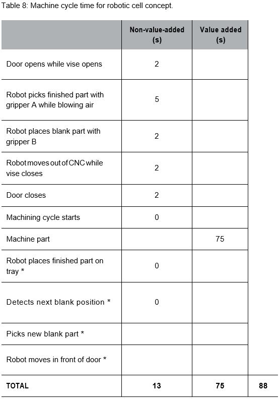
4. DESCRIBE PROCESS
Fig. 34 describes the overall process.

The different steps are listed in Table 8. The steps identified with a * are done at the same time as the part machining, so their time does not add to the total process time, and hence their time is 0.
In the manual task, the machine cycle start step took 2 seconds because the operator had to push the button, but here it takes 0 seconds because it is done using an I/O signal (hence start time is immediate).
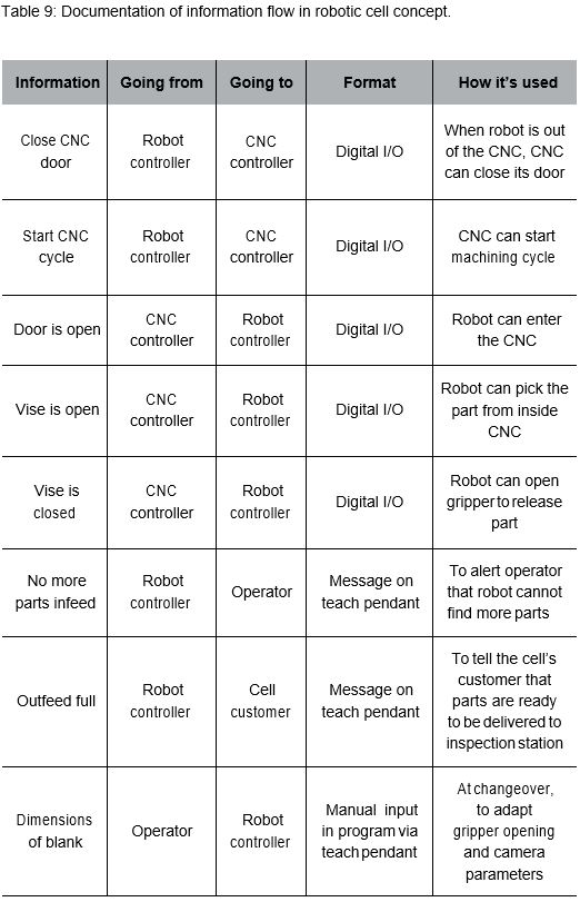
5. DOCUMENT FLOW OF INFORMATION
Table 9 summarizes the information needed at the cell.
6. TARGET CELL KPIs
What is the target KPI?
→ The KPI is the number of parts machined per day. The target number is up to 300 parts per day. (This is achievable with a shorter cycle time, cell running con- stantly during the day, and one input tray machined while unattended overnight.)
Acme would also like to maintain a first pass yield (FPY) of 97%.
How will the KPI be measured?
→ Using a counter in the robot’s program.
7. SUMMARIZE MAP
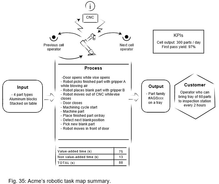
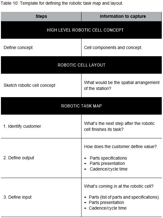
SUMMARY
Table 10 summarizes the steps that are executed to define the robotic task map after the high-level robotic cell concept has been defined.

Read Part 1 HERE.
Get the complete eBook HERE.
Samuel is CEO and co-founder of Robotiq. His mission is to free human hands from repetitive tasks. He is also the author of Lean Robotics: A Guide to Making Robots Work in Your Factory. He lives in Québec City with his wife and four children.