Electromate: Spring Applied & Power-Off Permanent Magnet Brakes – Engineering Failsafe Motion Control
August 19, 2026
Engineering Failsafe Motion Control: How to Determine Whether Spring Applied Brakes or Power-off Permanent Magnet Brakes Are the Right Choice for a Given Application
Most electromagnetic brakes work on a simple logic: apply current, apply braking. Remove current, release braking. For many industrial applications, conveyors, packaging lines, printing machines, this is exactly the right behavior. The brake engages on demand and releases when not needed.
But for a significant class of machines, this logic is exactly backwards. Robots, vertical servo axes, medical positioning systems, overhead cranes, mobile equipment, and any machine where an uncontrolled motion event during a power failure could injure a person or destroy a process: these applications require the opposite: braking must be the default state, and power must be used to release the brake, not to apply it.
This is the domain of failsafe brakes. Ogura manufactures two distinct failsafe brake technologies: spring applied brakes and power-off permanent magnet brakes, each with specific engineering advantages that determine which is the right choice for a given application. Understanding the difference is essential for engineers designing safety standards, and for procurement teams specifying brakes for safety-critical machines.
Why Standard Power-On Brakes Are Not Enough
A standard electromagnetic brake requires a continuous, active electrical signal to maintain brake force. The moment that signal is interrupted by a power failure, a broken wire, a blown fuse, an emergency stop relay opening, the brake releases. For a horizontal conveyor, that might be harmless. For a robot arm holding a tool above a workpiece, or a vertical axis holding a load against gravity, or a crane holding a suspended load, it is a potentially catastrophic failure mode.
Safety standards in robotics (ISO 10218), medical devices (IEC 60601), and lifting equipment (various national and international standards) explicitly require that braking occur on loss of power for any axis where uncontrolled motion creates a hazard. Power-on brakes cannot meet this requirement. Failsafe brakes can and in these applications, they are the only compliant choice.
Spring Applied Electromagnetic Brakes
Operating Principle
Spring applied brakes (also called spring set brakes or power-off brakes in older literature) use a stack of compression springs to provide the engagement force. The springs are preloaded between the field housing and the armature, pressing the armature against the friction surface at all times. To release the brake and allow rotation, the coil is energized – generating magnetic force that overcomes the spring preload and pulls the armature away from the friction surface.
The logic is: springs on = braking. Coil energized = released.
This produces inherently failsafe behavior. Power loss collapses the magnetic field, the springs immediately re-engage the armature against the friction surface, and braking is applied regardless of the cause of the power interruption. The brake does not require a controller to command it, a relay to close, or any active logic to execute the safe state. Physics handles it automatically.
Ogura’s MCNB series represents the current-generation spring applied brake design. It is available in 24 VDC, 45 VDC, and 90 VDC configurations. The 45 VDC type can be operated on half-wave rectification of 100 VAC – a useful integration option when a full-wave rectified DC supply is not available in the control cabinet. The friction material is engineered for a high coefficient of friction with superior wear resistance, delivering high torque and long service life. A standard D-cut metric bore is available in current series models.
Engineering Specifications
- Available Voltages: 24 VDC, 45 VDC (100 VAC half-wave compatible), 90 VDC
- Bore: Standard D-cut metric bore in current series
- Friction Material: High-coefficient, high-wear-resistance compound for long service life
- Holding Torque: Determined by spring preload – defined at manufacture, independent of electrical supply
- Release Torque (Coil): Must exceed spring preload with adequate margin across full temperature range
The Two Torque Values Engineers Must Calculate
Sizing a spring applied brake requires two separate, independent calculations that are often confused or conflated:
- Holding Torque: The torque the engaged springs must resist. This is the load the brake must hold when fully engaged and the coil is de-energized. For vertical axis applications, this is the gravitational torque on the load plus any required safety margin. Select the spring applied brake model whose rated holding torque exceeds this value.
- Release Torque: The torque the coil must generate to overcome the spring preload and release the brake. This must be evaluated across the full operating temperature range of the application, because spring preload increases as the spring rate interacts with thermal expansion, and coil force decreases as coil resistance rises with temperature. A brake that releases cleanly at 20°C may fail to release at 80°C if temperature effects are not accounted for in sizing.
Ogura provides torque characteristic curves for each series. Always confirm release margin across the expected operating temperature range during the sizing process.
Thermal Management During Release
When a spring applied brake is released (coil energized), the coil carries continuous current. This generates resistive heating in the coil. In applications where the brake is released for extended periods, a robot joint that spends most of its cycle in motion with the brake released, coil temperature rise must be evaluated. Ogura provides thermal ratings for continuous coil energization; exceeding these ratings degrades coil insulation and shortens service life.
For applications where the coil is energized for long periods, consider whether a rectified, regulated DC supply can reduce holding current after initial release. Many spring applied brake applications use a two-stage coil drive: a higher voltage for fast engagement (pull-in), followed by a lower holding voltage that reduces steady-state power dissipation.
Key Application Industries
- Industrial Robots and Cobots: Joint braking at each axis, ISO 10218 compliance
- Servo Motor Integral Brakes: Factory-installed on servo motors for vertical axis applications
- Medical Positioning Equipment: Patient tables, imaging system positioning, powered surgical platforms
- Radio Telescope Drives: Ogura spring applied brakes are used in radio telescope dish positioning systems where loss of holding torque during a power event could damage the antenna structure
- Overhead Cranes and Hoists: Emergency braking on loss of drive power
- Construction and Mobile Equipment: Winch brakes, boom lock, mobile utility vehicle drives
- Stage Machinery: Counterweight and flying systems where uncontrolled descent is a life safety hazard
Power-Off Permanent Magnet Brakes
Operating Principle
The permanent magnet power-off brake achieves the same failsafe logic as the spring applied brake — de-energized equals engaged — but uses a permanent magnet in place of mechanical springs as the engagement force source.
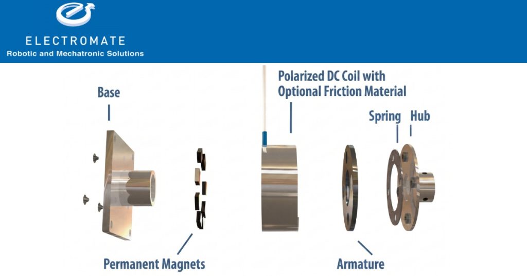
The permanent magnet is embedded in the field housing. Its field continuously attracts the armature against the friction surface. To release the brake, the coil is energized — generating a magnetic field that opposes and cancels the permanent magnet’s field. With the magnet’s attractive force neutralized, the armature moves away from the friction surface and the shaft is free to rotate. Remove coil power, the canceling field collapses, the permanent magnet re-engages the armature, and braking is applied.
The engagement energy source is magnetic, not mechanical. There are no springs to fatigue, no spring rate changes with temperature cycling, and no mechanical parts to wear or break in the engagement mechanism. This is a fundamental reliability advantage over spring applied designs in applications with very long service intervals or extreme thermal cycling.
The Energy Consumption Advantage
This is the decisive engineering advantage of permanent magnet power-off brakes in battery-powered and energy-sensitive applications: the brake consumes electrical power only when it is releasing (coil energized, shaft rotating freely). In the engaged state, holding a load, maintaining position, the permanent magnet provides all the holding force with zero coil current, zero power consumption.
Compare this to a spring applied brake, which also consumes power only during release. So far, identical. The difference emerges in the coil power required: permanent magnet designs can achieve the same holding torque with significantly less release coil power than spring applied equivalents, because the coil only needs to cancel the magnet field (which scales favorably with design), not overcome a full spring preload.
Ogura’s MPNC-3.5, for example, operates at 2.4 W, dramatically lower than equivalent spring applied designs. In a mobile robot with 6 axis joints, each fitted with a permanent magnet power-off brake, the energy budget difference across a full shift is substantial.
Thermal Advantages
Lower coil power during release means lower coil temperature during the release state. In compact robotic joints and small servo brake packages where thermal management is constrained by the mechanical envelope, this can be the deciding factor between a permanent magnet design and a spring applied design. Less heat generated means smaller required thermal mass, better sustained performance, and longer coil insulation life.
Design Simplicity
Permanent magnet power-off brakes are also mechanically simpler than spring applied designs. Fewer components, no spring stack to assemble and tension, and no spring fatigue mechanism means fewer failure modes. This translates to higher reliability predictions in MTBF calculations for safety-critical designs.
Key Application Industries
- Autonomous Mobile Robots (AMRs) and AGVs: Failsafe wheel braking with minimum battery drain; critical for vehicles operating across full shift without recharge
- Collaborative Robots (Cobots): Compact joint braking; permanent magnet designs fit more easily in the constrained link envelopes of cobot arms than spring applied equivalents
- Servo Axis Brakes for Energy-efficient Machines: Any multi-axis machine where reducing servo brake power consumption contributes to overall energy efficiency targets
- Medical Devices Requiring Compact and Low-heat Brake Design: Implant assembly machines, surgical robot brakes, diagnostic imaging positioning systems
- Semiconductor and Electronics Manufacturing: Cleanroom servo axes where heat generation affects process temperature control
Spring Applied vs. Permanent Magnet: Choosing Between Them
Both technologies deliver failsafe braking. The decision comes down to four factors:
- Torque Range: Spring applied brakes cover a wider torque range in the Ogura catalog. For very high torque requirements, spring applied is typically the available option.
- Power and Thermal Budget: If coil power consumption during the release state matters, battery-powered equipment, tight thermal envelopes, energy efficiency requirements, permanent magnet designs win consistently.
- Temperature Cycling and Service Life: Permanent magnet designs have no spring fatigue mechanism and no spring rate drift with temperature cycling. For very long service intervals (10+ years without maintenance) or extreme thermal environments, permanent magnet designs offer a reliability advantage.
- Cost: Spring applied brakes are generally lower cost at equivalent torque. For applications where none of the above factors favor permanent magnet designs, spring applied remains the standard choice.
A Note on Emergency Stop vs. Holding Brake
Engineers specifying failsafe brakes for servo axis applications should understand the difference between two distinct functional requirements:
- Holding Brake: Holds a stationary load when the drive is powered down. The brake engages at zero speed. No deceleration energy is absorbed. This is the appropriate specification for vertical axis holding, robot joint locking at end of cycle, and position maintenance during power-off.
- Emergency Stop Brake: Must decelerate a moving axis to zero. Absorbs kinetic energy during stopping. This is a higher thermal demand than a holding brake — the energy absorbed during each emergency stop heats the friction surfaces. Emergency stop brake sizing requires thermal analysis of the worst-case stop scenario, including the energy to be absorbed and the allowable number of consecutive stops before thermal limits are reached.
Both spring applied and permanent magnet power-off brakes can perform either function, but if the application requires repeated emergency stops from running speed, the thermal analysis is critical and must be performed before finalizing the specification.
Related Products
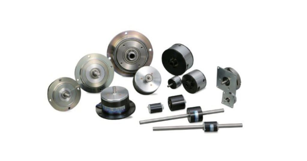
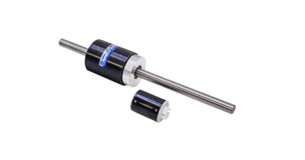
- PMB Series Electromagnetic / Permanent-Magnet Brakes
- PHT Series Permanent-Magnet Brakes
- OPL Series Permanent-Magnet Brakes
For more information on Electromate solutions HERE


Failsafe Motion Failsafe Motion Failsafe Motion Failsafe Motion Failsafe Motion Failsafe Motion Failsafe Motion Failsafe Motion Failsafe Motion Failsafe Motion Failsafe Motion Failsafe Motion Failsafe Motion Failsafe Motion Failsafe Motion Failsafe Motion Failsafe Motion Failsafe Motion Failsafe Motion