Mouser: Machine Safety Best Practices in Industrial Automation

April 29, 2026
Machine Safety: How to Implement Functional Safety, Risk Assessment & Protective Measures in Automated Systems
By: Abhishek Jadhav
The most critical requirement in an industrial plant, particularly those operating heavy machinery or complex automated systems, is a robust safety program. While modern automation brings significant productivity and efficiency benefits, it also introduces potential hazards to operators, maintenance personnel, and anyone working near automated equipment.
Effective machine safety in industrial automation requires a systematic approach that combines adherence to industry standards, comprehensive risk assessments, and the implementation of engineering safeguards. These safeguards must be integrated into machine design and control systems to minimize hazards while maintaining operational efficiency.
This article explores machine safety best practices in industrial automation, outlining how risk assessment, functional safety standards, and safety- and performance-level targets guide the design of reliable safety functions. It also explains how common safety equipment and standards-based implementation helps protect personnel while maintaining system performance.
Steps to Implement Machine Safety
Implementing safety in an automation environment starts with a structured functional safety life cycle. This process includes identifying hazards, assessing risks, reducing those risks through engineered safeguards, and continually validating and maintaining machine safety.
International standards provide frameworks for implementing best practices. For instance, International Organization for Standardization (ISO) 12100 gives principles for machinery risk assessment and hazard reduction, while standards such as ISO 13849 and International Electrotechnical Commission (IEC) 62061 define requirements for safety-related control systems. In process industries, IEC 61508 and IEC 61511 govern functional safety and safety instrumented systems (SIS), respectively.
Assess Hazards & Risks
Risk assessment begins by identifying potential hazards associated with machinery or processes. These hazards may include mechanical risks (e.g., crushing or pinch points), electrical hazards from energized components, pneumatic or hydraulic pressure failures, or chemical and thermal hazards.
After identifying the hazards, engineers must evaluate the severity and likelihood of each to determine the required level of risk reduction. The objective is to determine whether additional safeguards are necessary and what type of safety function is required.
Standards like ISO 12100 and American National Standards Institute (ANSI) B11.0 guide this process for machinery safety. For instance, a risk assessment might identify pinch-point hazards on a conveyor system, collision risks in robotic work cells, or overpressure conditions in a reactor vessel. This assessment is intended to determine which hazards require engineered protective measures.
Apply the Hierarchy of Controls
Risk mitigation follows the hierarchy of controls that prioritizes hazard-reduction methods by effectiveness. The preferred approach is to eliminate hazards or substitute safer alternatives during the design stage. If elimination is not possible, engineers must implement engineering controls to isolate operators from hazards. Engineering controls include physical guards, interlocks, safety circuits, and automated shutdown systems that can prevent an incident without relying on human intervention.
Design & Integrate Safety Functions
Once engineers have assessed the hazards, they must implement safety functions within the machine control systems to achieve the required level of risk reduction. Safety functions monitor critical inputs, such as guard position, emergency stop activation, or intrusion detection, and automatically transition the system to a safe state when hazardous conditions are detected.
These functions are implemented using safety-related control systems, which may include safety relays, safety programmable logic controllers (PLCs), or certified motion controllers. Safety functions are designed to be fail-safe, meaning that a fault condition (e.g., a wire break or power loss) causes the system to default to a safe state.
Reliability is increased through redundancy and diagnostics. For example, many safety circuits use dual-channel architectures with cross-monitoring, so that if one channel fails, the other can still trigger a stop.
Functional safety standards quantify reliability using constructs like Safety Integrity Levels (SIL; Table 1) or Performance Levels (PL).
Table 1: SIL determined by probabilities showing the likelihood that a safety function will fail when required.
| Safety Integrity Level | Average probability of failure on demand (PFDAVG) in low demand mode of operation | Probability of failure per hour (PFH) in high demand mode of operation |
| SIL 1 | ≥ 10-2 to < 10-1 | ≥ 10-6 to < 10-5 per hour |
| SIL 2 | ≥ 10-3 to < 10-2 | ≥ 10-7 to < 10-6 per hour |
| SIL 3 | ≥ 10-4 to < 10-3 | ≥ 10-8 to < 10-7 per hour |
| SIL 4 | ≥ 10-5 to < 10-4 | ≥ 10-9 to < 10-8 per hour |
A PFDAVG of 10-3 (SIL 2) means the safety function has a target average probability of failing once in every 1,000 demands. The engineer must determine whether this level of risk is acceptable for the specific hazard. If the consequences of failure are severe, resulting in injury, explosion, or major equipment damage, SIL 2 may not be sufficient. In such cases, a higher SIL may be required.
Engineers must ensure that this failure rate is sufficiently low for the application’s risk level. This is achieved by analyzing component failure rates (Table 2), common cause failures, and diagnostic coverage to verify that the safety function meets the required target failure probability.
Table 2: Probability of failure during continuous operation.
| Performance Level | Average probability of failure per hour (PFH) |
| PL a | ≥ 10-5 to < 10-4 per hour |
| PL b | ≥ 3 x 10⁻⁶ to < 10-5 per hour |
| PL c | ≥ 10-6 to 3 x 10⁻⁶ |
| PL d | ≥ 10-7 to < 10-6 per hour |
| PL e | ≥ 10-8 to < 10-7 per hour |
For instance, a system designed to attain PL d with a PFH of 10-7 implies that a failure may occur once every 10 million operating hours. Therefore, engineers can use these ranges to determine the risk reduction provided by a safety function and to ensure the system is reliable for the level of hazard exposure.
In contrast to SIL, achieving a PL is not based solely on the probability of failure. While both SIL and PL use probabilistic targets, ISO 13849 requires that the target PL be achieved through a combination of system architecture (Category), component reliability according to mean time to dangerous failure (MTTFd), diagnostic coverage, and protection against common cause failures.
Ensure Standards Compliance & Certification
Compliance with safety standards is important for reducing risk and meeting regulatory and legal requirements.
In Canada, machine safety compliance is governed by various standards and regulations, including the CSA Z432 and NFC 2020 fire safety codes. These standards cover aspects such as machine safety, lockout/tagout procedures, and environmental regulations. Compliance is essential for ensuring safe working conditions and protecting workers from hazards.
In the United States, regulations from the Occupational Safety and Health Administration (OSHA) mandate practices such as machine guarding and lockout/tagout (LOTO) procedures to control hazardous energy. In the European Union, machines must comply with the Machinery Directive and meet CE marking requirements by adhering to harmonized standards.
Safety components must also be certified by independent organizations, such as the German-based TÜV, to verify compliance with functional safety standards. For instance, a safety controller may be TÜV-certified for use in applications up to SIL 4 or PL e, indicating that the device meets the highest reliability criteria defined by IEC 61508 and ISO 13849.
Validate & Maintain Systems
After implementing safety measures, engineers must validate the automation systems to confirm that all safety functions operate as intended. Validation ensures that sensors, interlocks, emergency stop devices, and other safety mechanisms detect hazards and initiate safe shutdown procedures. In many systems, engineers must perform formal verification tests to confirm that safety functions achieve the required SIL or PL targets.
Safety systems also require ongoing maintenance and periodic testing. Preventive inspections ensure that safety devices remain operational, properly calibrated, and free from bypasses or unauthorized modifications. For example, maintaining an SIS in a process plant requires technicians to routinely proof-test sensors, logic solvers, and shutdown valves to ensure they will respond correctly during an emergency.
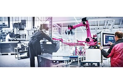
Machine Safety Equipment
Companies use a wide range of safety devices and control components to implement protective measures in industrial automation systems. These devices are designed to either prevent operators from entering hazardous areas or to detect unsafe conditions and automatically stop the automated system.
Physical Guards & Safety Interlocks
Physical guards are among the most common safety measures used in industrial machines. Fixed barriers, such as metal or polycarbonate enclosures, prevent operators from accessing moving parts or hazardous mechanisms. For machinery that requires regular access for maintenance or operations, interlock switches ensure that the machine stops before the guard can be opened. For example, a computer numerical control (CNC) machine may include an interlocked door mechanism that immediately cuts power to the spindle and axes when the door is opened.
Interlock devices come in several forms, including switches, relays, and logic-controlled devices. All serve the same function of linking the machine’s operating state to the position of a physical guard.
Emergency Stop Devices
Emergency stop (E-stop) devices are mandatory on most industrial machines. These are red panic buttons that allow operators or nearby personnel to shut down the equipment immediately in an emergency.
E-stop devices are usually integrated into the machine’s safety control circuit and monitored by safety relays or controllers. In large or linear machinery like conveyors, E-stop pull cords may also be installed to allow workers to stop the equipment from any point along the system.
Safety Mats & Edges
Safety mats and safety edges provide contact-based protective sensing for industrial environments. A pressure-sensitive safety mat contains embedded sensors that detect the presence of a person standing in a monitored zone. If weight is applied to the mat, the safety control system stops the machine right away. These devices are commonly installed around robotic work cells or hazardous machinery where physical guarding is impractical.
Safety edges are used on moving equipment, such as automated guided vehicles (AGVs), machine doors, or powered gates. When the edge makes contact with an object or person, the system triggers a stop or reversal motion to prevent injury. These contact-based solutions are used alongside non-contact protective devices like safety light curtains or laser scanners.
Controllers & PLCs
Safety controllers serve as the decision-making element of modern safety systems. Simpler machines may use dedicated safety relays that monitor safety inputs (e.g., emergency stops, guard switches, light curtains). These relays detect faults with built-in diagnostic functions, including pulse testing and feedback-loop monitoring. More complex automation systems rely on safety PLCs designed to meet functional safety requirements. These devices incorporate features such as redundant processors, continuous diagnostics, and certified safety logic blocks.
Safety PLCs allow multiple safety inputs and outputs to be evaluated using validated safety logic. This enables engineers to implement complex safety strategies across large automated systems while maintaining compliance with functional safety standards.
Conclusion
Machine safety relies on a comprehensive combination of risk assessment, engineered safeguards, and standards-based control system design. By following the structured safety methodologies and implementing certified safety devices, engineers can significantly reduce operational risk in dynamic automation environments.
For more information on Mouser Electronic solutions HERE

Machine Safety Machine Safety Machine Safety Machine Safety Machine Safety Machine Safety Machine Safety Machine Safety Machine Safety Machine Safety